Natural Resource BiometricsLog Volume EstimationLog volumes can be estimated in a number of ways. Most methods estimate different portions of the log volume using different formulas. Figure 1 below indicates the most commonly used formula for each portion of a tree. 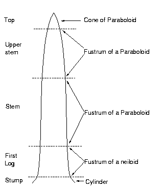 Each of these sections of the stem can be estimated using one of four basic equations;
 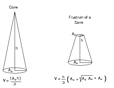
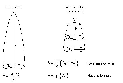
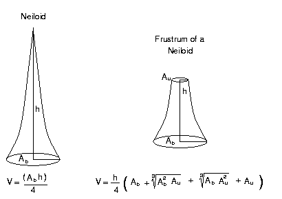
For the same input data these volumes will order this way:
Diagram Log Rules Diagram Rules are volume rules that depend on a saw pattern and assumed kerf (width between the boards, see Figure 6). 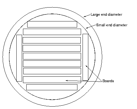 The most common diagram rule is the Scribner log rule. The Scribner was proposed by J. M. Scribner and first published in 1846 (Husch et al. 1993). It assumes a 1/4 inch kerf and 1 inch boards probably not less that 8 inches wide. (Chapman and Meyer, 1949). The Scribner log rules are for logs with small end diameters from 12 to 44 inches and 10 to 24 feet in length. Bruce and Schumacher (1950) fit a regression equation to the original table an produce the following equation:
D is small end diameter in inches, L is log length in feet.
overrun decreases up to 28 inches where is flattens out at about 3- 5 %. Mathematical Log Rules Doyle Log Rule This is one of the most widely use and well as one of the oldest log rules. The rule was developed by Edward Doyle in 1825. The rule states:
This equivalent to squaring the log into a cant and calculating the board feet in the cant. Doyle assumed 25 % reduction for kerf and shrinkage. The rule can be stated as:
D is small end diameter in inches, L is log length in feet.
The rule works best for logs between 26 and 36 inches in diameter; Larger logs produce underruns, Smaller logs produce high overruns. International log rule One of the most accurate mathematical log rules was proposed by J. F. Clark (1906). The log rule was developed for 4 foot sections of a log. It assumes a 1/8 inch kerf and a 1/16 inch shrinkage. Clark suggested a 1/2 inch taper per 4-foot section of log and so came up with the following formulas: Clark suggest that logs larger that 20 feet be measured as multiples of one of these log lengths. Also See: Chapman, H. H. and W. H. Meyer. 1949. Forest Mensuration. McGraw-Hill Book Co. New York. 522 pp.,/p> Clark, J. F. 1906. Measurement of Sawlogs.Forestry Quart. 4:79-93. Chapter 8 in : Husch, B., T. W. Beers and J. A. Kershaw. 2003. Forest Mensuration. Fourth Edition. John Wiley and Son 443 p. |
 This work is licensed under a Creative Commons Attribution-Noncommercial 3.0 United States License. Author: Dr. David R. Larsen Created: September 6, 2000 Last Updated: December 15, 2019 |